
The Phantom Vision 2+ was meant to be my "canary" - to be the craft I experiment with before trying it out with the Cannes Phantom or the S1000.
As it turns out, this wasn't a good idea. The Vision 2+'a tight integration makes it great for out of the box FPV and filming but it also means that you can't take "standard" (at least for DJI ships) parts and modify/upgrade it.
A now non-negotiable feature for my canary is robust flight telemetry logging. The DJI iOSD Mark II provides telemetry logging but the module isn't compatible with the Vision 2+.
The need for a more modular, easier to fix, upgradable, tweak-able canary has led me to the DJI F550 "Flame Wheel."
I'm outfitting it with the Naza V2+GPS, iOSD Mark II, AVG58 video and 2.4 Ghz data link. This will give me a facsimile of the S1000 (minus the monster A2 flight controller) and the Cannes Phantom. Before I try anything risky with those two, the Canary will try it first.
(A tinsy 3.1 micro controller decoding DJI CAN-bus data and integrating it with a wack of temperature sensors might be a good first project - but I digress)
Parts list:
- DJI F550 Flame Wheel Kit
- Naza V2/GPS combo
- Turnigy 9xr transmitter
EZ UHF 433Mhz transmitter/receiver (my ham call sign: KD0HMT(EZUHF build quality so poor it is unredeamable. Might use it in the FliteTest BatBone.)- Spektrum DX9 and AR8000 Receiver
In the kit

Motor in the bag

DJI 2212, 920KV motors
IMPORTANT Tip: The motors with the dot on the motor axle are clockwise motors. Those with out the dot are counter clockwise. Pay attention the the order of clockwise and counter clockwise motors: M1-CCW, M2-CW, M3-CCW, M4-CW, M5-CCW, M6-CW.

Pay attention to the dots on the motors: the the threads for the props only self tighten if you've got a dotted clockwise motor in the clockwise motor position (M2, M4, M6).

Some cheapy props
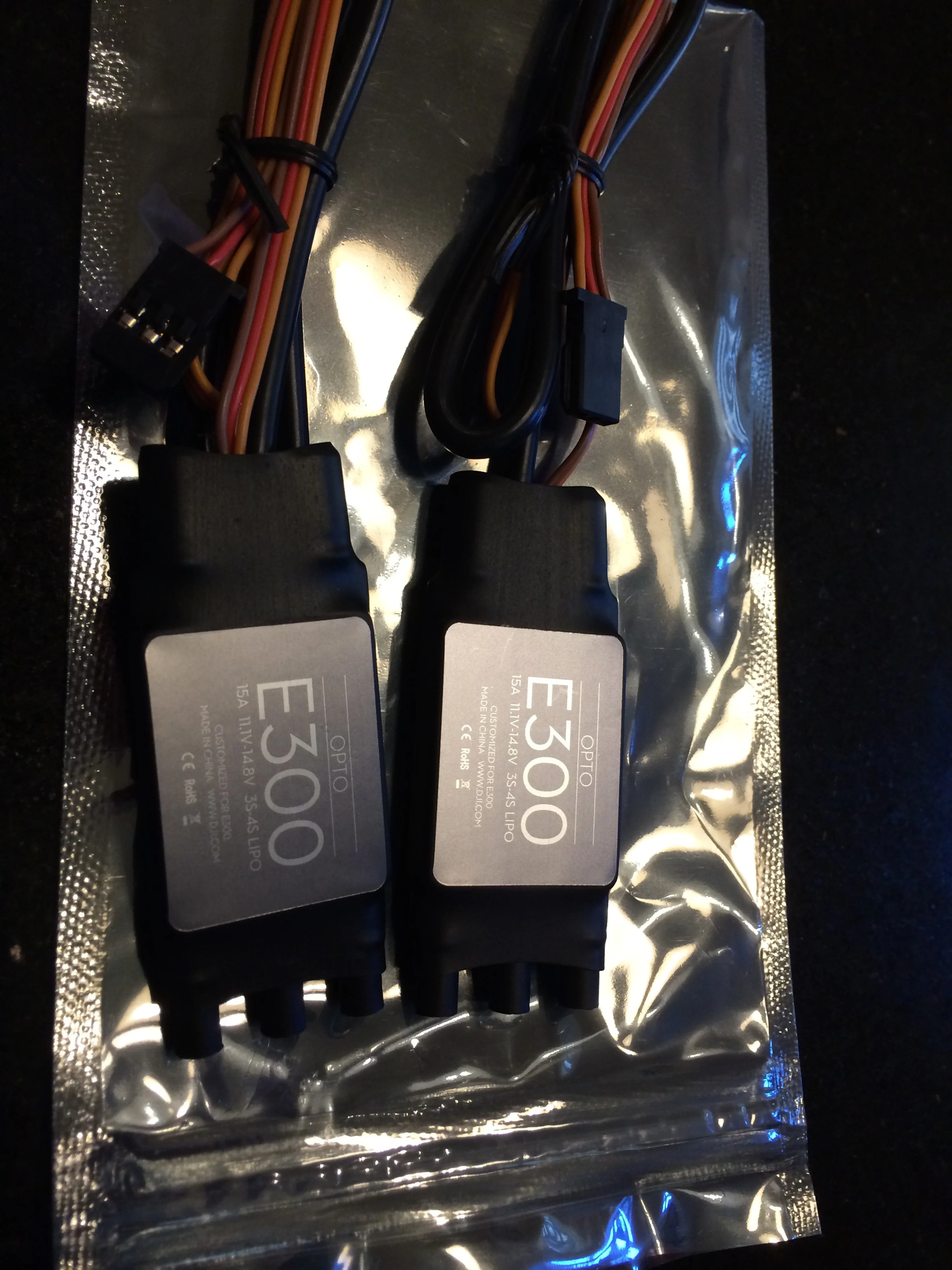
Opto E300, 15A 11.1-14.8V 3S-4S Lipo
Allegedly, there's no parameters or calibration to be done with these ESCs as they're customized to work with DJI auto pilots.

Top and bottom center plates. The bottom plate is also the power distribution board.

Arms
Building
Attaching Motors

Loctite each screw. (Yes, I'm making a mess)

Attach the motors to each arm

All six complete. Now for the ESCs.
Prepping the ESCs
- trim back the ESC power wires
- tin the trimmed ESC power leads
- tin the power distribution pads, flux em and tin em
- check each solder joint for cold joints

ESCs attached... Now to inspect each joint.

Joints for ESC 1

Joint 2

Joints for ESC 3

Joints for ESC 4

Joints for ESC 5

Joints for ESC 6
Next, attach the legs and zip tie the ESCs to the arms.

I probably should trim down those ESC power lines... It looks messy.
Battery Terminals
The iOSD needs to share battery with the Naza V2 and comes with a sort of Y-cable with XT60 connectors on it.
My original thought was to just go with the XT60s but I bought 4S 30C 5000mah batteries for the F550. They're equipped with 10 gauge wire - too big for XT60s. Besides, soldering (well) 10 gauge braided wire is not my idea of fun.
I ditched the XT60s in favor of Anderson Power Poles. I use them on my ham radios and they're phenomenal. I used the 45A version and a crimp tool - fast, extremely secure, and reliable.
I will keep the XT60s on my 3S 2200mah batteries used for the radio, Flite Test Bat Bone and AnyCopter quad.

Anderson Power Poles for the battery connections.

Anderson Power Pole crimp tool
Now for the Brains
I don't want to install the iOSD, AV58 and Datalink right away - get it flying first then pimp it out.
Never the less, I need to layout all the parts so I know where to attach the basic parts in a way that leaves room for the additions.

As an after thought - or a thought just before it's too late - I put some red liquid electrical tape over the power distribution board solder joints.

Big sloppy blobs of liquid electrical tape on the pads.

All brains mounted with Scotch Extreme Mounting Tape.
I've ordered a right angle micro USB cable for the iOSD Mark II. If that doesn't work out, I will need to relocate or reorient the iOSD so the serial port is accessible. Recall that a significant part of the reason I'm building the 550 is to experiment with the on board flight logging on the iOSD Mark II.
Assembling a Battery Cable
I need the battery to connect to two places: first to the power distribution board (bottom plate of the F550) and second to the Naza PMU. So I'll just solder two wires to the power distribution board pads.
This turned out to be a bigger challenge than I'd expected. Below is an image of my first failed attempt. Notice the discolored wire and the lack of solder penetration. I just couldn't seem to get these two pieces of 10 gauge wire hot enough to get solder to flow - while at the same time baking them into a carbonated mess and melting the insulation. Further, somehow I needed to get this mess soldered to the power distribution board. (Yes, I bathed the wire in flux, I tinned my 60W iron, I had a bead between the iron and the wire opposite the solder to wire contact.)

First failed attempt at a battery cable.
I went in search of advice. First to ActionRC hobbies. No luck on solving the solder problem. But did find this nifty connector vice. It made soldering XT60s a breeze - well worth the $15.

I don't know who manufactures this.

Nifty connector vice made soldering XT60s a breeze
Next, to Radio Shack. If you just chuckled, yeah you were right (this time.) When I asked about my soldering issue the blank faces of the sales guys told me I might as well have just asked them if they could help decypher some hieroglyphics.
Next, Home Depot. Maybe there an electricians trick for heavy gauge wire. There is and it's called wire nuts. However, I can't trust my drone's power supply to a plastic cap that almost certainly will vibrate loose.
As a last ditch effort, there was a different Radio Shack next to the Home Depot. Jackpot. The sales guy here was an old school geek that built Heathkit radios and Hero robots. He sold me $8 worth of really thin solder - maybe 20 gauge thickness. He suggestd that my 12-14 gauge solder requires too much heat. Went home and tried it: bingo! Beautiful flow.
i took a different tack this time around. Instead of trying to join 3 bulky parts at the power distribution board pad, I stripped a short section of the main battery wire insulation from the middle of the wire and joined the Naza power connector there. This way there was only one wire to attach to the power distribution board pad, and two wires to join in the middle of the battery wire.

New battery cable approach
The final attached cable had Anderson Power Poles for the battery and an XT60 for the Naza PMU. I used liquid electrical tape on the back of the XT60. Why? Because in my excitement that the cable was coming together and how nifty the connector vice was - I forgot to put the heat shrink on the wire before soldering. Rather than re-solder, I used the liquid electrical tape.

Final cable attached to power distribution board. I stuck a sheet of paper behind the cable for the picture . Otherwise it was visually lost in the rats nest of wires behind it.

Attached to top plate. Notice the GPS tower mount is attached using the top plate screws. I had to Dremel out two of the holes to make that possible.

All screws bathed in Locktite 242.

GPS tower base plate mounted with top plate screws.
GPS Tower attached to base plate and GPS/Compass unit using 30 minute epoxy.

Great Planes 30 Minue Pro Epoxy

Epoxy on tower rod and base plate.

Epoxy on GPS tower and GPS-compass sensor.
The little orange arrow on the GPS-compass unit has to point toward the forward direction of the copter. The epoxy provides zero friction for the first 20 minutes or so before it "sets-up." This made it challenging to keep the GPS pointed in the right direction while the epoxy dried. I ended up taping down the connector cord as a way to keep it still while I worked on other parts of the craft.
Attaching the Skids

Attached skids. I don't know the manufacturer - I bought these from a friend.

Skids attach using 4 of the bottom plate to arm screws.

Skids attachment screws. Dowsed in Locktite 242 Blue as usual.
The skids provide a nice place to mount the BlueTooth data link and 2.4Ghz data link radios.

Bluetooth transceiver.
5.8Ghz Video Transmitter
The video transmitter is attached using the Scotch Extreme double sided tape. I want a zip tie on here too but couldn't an orientation that wouldn't put torque on the mounting tape.

Video transmitter. (DJI AV58)

Scotch Extreme double sided mounting tape.
Setting Up The Naza V2
Now that the F550 is starting to look like a drone, it's time to start dealing with the brains.
<< Insert Description of Naza Settings >>
<<motor tests>>
Setting Up The Spektrum DX9
<< Explain ditching the EZUHF >>
<< Insert Description of DX9 Setup >>