Death of Phantom

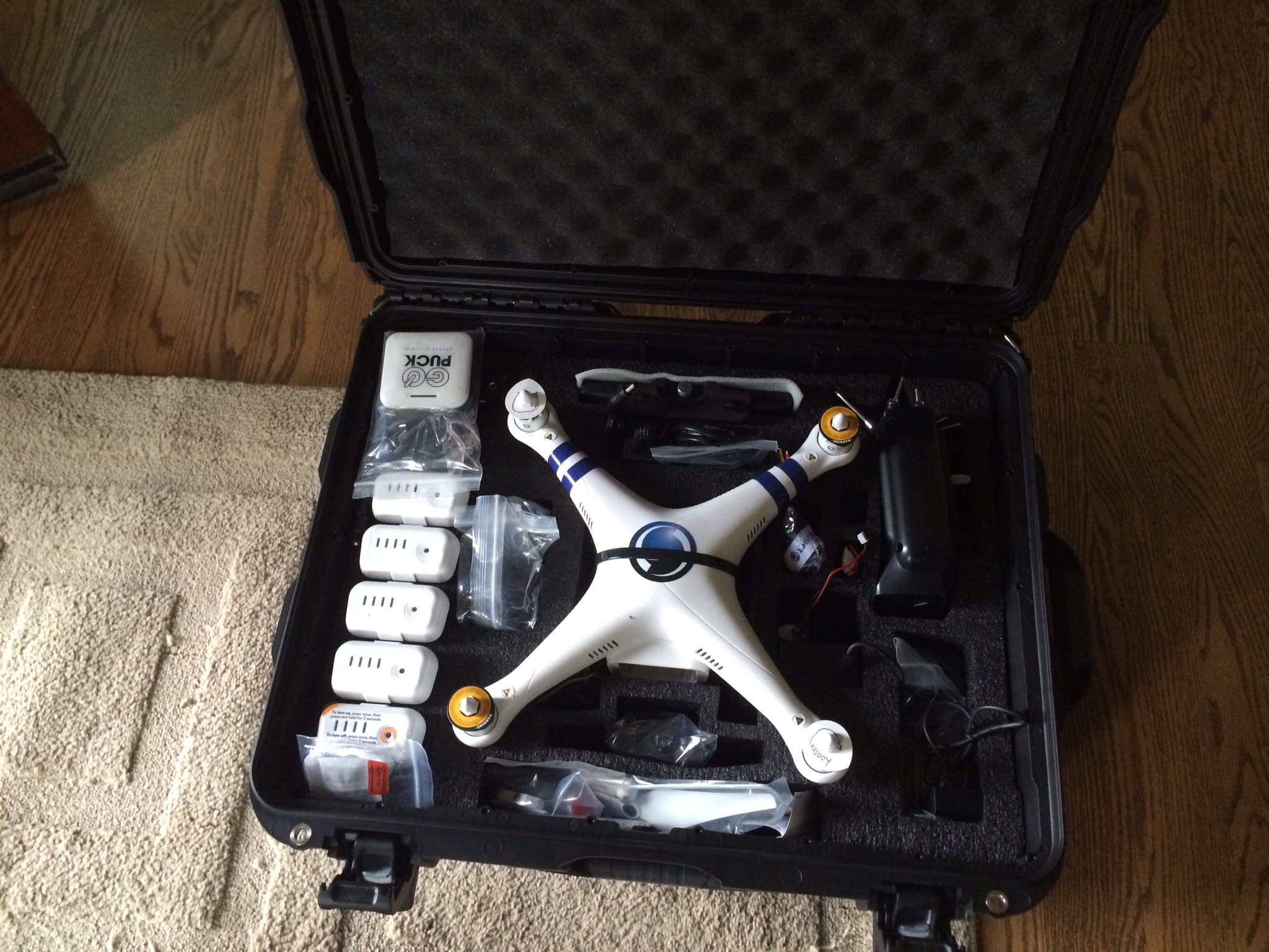
My new Phantom 2 Cannes Edition  arrived from DSLRPros last week. (See earlier blog post)

Shephard, who's going into this crazy business with me, just got his new Phantom. We were getting together to try out his new phantom, show off the flame wheel, and for him to see the Cannes. This was its fourth flight. It did phenomenally well. Right up untiit did somersaults into a giant rock. 

It had gracefully completed a wide turn, straightened out and started coming home. After an unpleasant "whack", it tumbled to the ground like a duck after meeting a cloud of shotgun pellets. 

I couldn't understand what I was seeing. Did it get hit by a bird? Was it shot down? 

I looked at Shep who had the same puzzled look on his face. 

Below is a frame of the video of the carnage. I'd post the video but it's over-full of my winded, post run, expletives. 

As we gathered up the wreckage, a picture of what happened started to emerge.

The first clue was that the Phantom only had three props attached.

The second clue was that all of the wreckage was in a 15 square foot area.  Except for the fourth prop.

The last clue was the white nut holding propeller on to the craft was 20 feet away from the rest of the wreckage. 

The fourth prop remains lost. It must have come off, sailed into one of the 3 remaing props to make that loud, hollow, sickening, nightmare inducing "whack!" heard before the death tumble. 

How did this happen? If you're familiar with these things, you know that the threads on the motors are either normal or reversed depending on whether they're attached to a clockwise or counter clockwise spinning motor. This way, when the motor spins it tightens the nut. Thus the name "self tightening nuts."

However, the Cannes comes with DSLRPros branded props that have flat surfaces inside the prop hub to grip the motor shaft. 

Flat sides inside the prop hub.

Flat sides inside the prop hub.

This creates a great torque transfer joint but removes any torque from the nuts. Without the torque and friction of the prop, they're just nuts tightened onto a spinning, vibrating post instead of self tightening.

So now I'm left with 4 thoughts: 

1) I should have checked those nuts between every battery.  

2) Is the DSLRPro prop so much better than some other design that losing the self tightening features makes sense? I have to lean toward "no" since this crash is going to cost $2,100 to fix. Even if I Loctite the prop nuts and check them between every battery, I still don't know they won't vibrate free mid flight. 

3) how many other prop designs use the flat sided hubs? Do they use cotter pins or some other fail safe?

4) Shep is a good dude. He offered to pay for half the repairs since this happened on his training session. No way he has any blame, no way I'd take his money, but very generous of him to offer.  

Moral of the story? Preflight obsessive compulsive checks are not optional. And, Loctite or replace your Cannes Edition or similar props.


DSLPRos Cannes Kit has Arrived

I am walking out the door to board a plane to Las Vegas for the Nevada Unmanned Systems Business Expo. What shows up just before I leave? The DSLRPros Cannes Kit uber-Phantom 2 kit. I don't have time to play with it - but wow is it a complete kit and I am impressed that EVERYTHING fits in this super rugged case.

Cannes kit case

Cannes kit case

I have a nice GoProfessional case for the Phantom Vision 2+, but this blows it out of the water. It's built like a tank and is a roller bag. DSLRPros was confident enough in it to ship the drone in the case (albeit with some zip-ties securing the gimbal - see black strap bisecting the Phantom shell.)

I'll followup when I get back from the Expo.

Poor Build Quality of the EZUHF JR Module

I wanted to compare the abilities of a EZUHF 70cm radio vs the 2.4Ghz radios. I picked up a Turnigy 9XR and a EZUHF JR module from Hobby King.

Shortly after they arrived, I gave them a try. I am dumbfounded by what happened next. The EZUHF JR module was apparently not getting power from the Turnigy. It clearly powered up when connected by USB - but showed no signs of life when plugged into the Turnigy.

After a little bit of googling, I found the following video on this thread.

This EZUHF module is the vital link between you and your drone - and THAT is the build quality. This is meant to be a long range transmitter. Can you imagine having your drone a mile up a mountainside and the flimsy little connectors break contact?!? Absurd! I can't see ever using these in a production drone. I am in shock.

Building the Flamewheel F550

The Phantom Vision 2+ was meant to be my "canary" - to be the craft I experiment with before trying it out with the Cannes Phantom or the S1000.

As it turns out, this wasn't a good idea. The Vision 2+'a tight integration makes it great for out of the box FPV and filming but it also means that you can't take "standard" (at least for DJI ships) parts and modify/upgrade it.

A now non-negotiable feature for my canary is robust flight telemetry logging. The DJI iOSD Mark II provides telemetry logging but the module isn't compatible with the Vision 2+.

The need for a more modular, easier to fix, upgradable, tweak-able canary has led me to the DJI F550 "Flame Wheel."

I'm outfitting it with the Naza V2+GPS, iOSD Mark II, AVG58 video and 2.4 Ghz data link. This will give me a facsimile of the S1000 (minus the monster A2 flight controller) and the Cannes Phantom. Before I try anything risky with those two, the Canary will try it first.

(A tinsy 3.1 micro controller decoding DJI CAN-bus data and integrating it with a wack of temperature sensors might be a good first project - but I digress)

Parts list:

  • DJI F550 Flame Wheel Kit​
  • Naza V2/GPS combo​
  • Turnigy 9xr transmitter
  • EZ UHF 433Mhz transmitter/receiver (my ham call sign: KD0HMT (EZUHF build quality so poor it is unredeamable. Might use it in the FliteTest BatBone.)
  • Spektrum DX9 and AR8000 Receiver ​

​In the kit

Motor in the bag

Motor in the bag


DJI 2212, 920KV motors

DJI 2212, 920KV motors

IMPORTANT Tip: The motors with the dot on the motor axle are clockwise motors. Those with out the dot are counter clockwise. Pay attention the the order of clockwise and counter clockwise motors: M1-CCW, M2-CW, M3-CCW, M4-CW, M5-CCW, M6-CW.

Pay attention to the dots on the motors: the the threads for the props only self tighten if you've got a dotted clockwise motor in the clockwise motor position (M2, M4, M6).

Pay attention to the dots on the motors: the the threads for the props only self tighten if you've got a dotted clockwise motor in the clockwise motor position (M2, M4, M6).

Some cheapy props

Some cheapy props

Opto E300, 15A 11.1-14.8V 3S-4S Lipo

Opto E300, 15A 11.1-14.8V 3S-4S Lipo

Allegedly, there's no parameters or calibration to be done with these ESCs as they're customized to work with DJI auto pilots.

Top and bottom center plates. The bottom plate is also the power distribution board.

Top and bottom center plates. The bottom plate is also the power distribution board.

Arms

Arms

Building

Attaching Motors

Loctite each screw. (Yes, I'm making a mess)

Loctite each screw. (Yes, I'm making a mess)

Attach the motors to each arm

Attach the motors to each arm

All six complete. Now for the ESCs.

All six complete. Now for the ESCs.

Prepping the ESCs

  • trim back the ESC power wires
  • tin the trimmed ESC power leads
  • tin the power distribution pads, flux em and tin em
  • check each solder joint for cold joints
ESCs attached... Now to inspect each joint.

ESCs attached... Now to inspect each joint.

Joints for ESC 1

Joints for ESC 1

Joint 2

Joint 2

Joints for ESC 3

Joints for ESC 3

Joints for ESC 4

Joints for ESC 4

Joints for ESC 5

Joints for ESC 5

Joints for ESC 6

Joints for ESC 6

Next, attach the legs and zip tie the ESCs to the arms.

I probably should trim down those ESC power lines... It looks messy.

I probably should trim down those ESC power lines... It looks messy.

Battery Terminals

The iOSD needs to share battery with the Naza V2 and comes with a sort of Y-cable with XT60 connectors on it.

My original thought was to just go with the XT60s but I bought 4S 30C 5000mah batteries for the F550. They're equipped with 10 gauge wire - too big for XT60s. Besides, soldering (well) 10 gauge braided wire is not my idea of fun.

I ditched the XT60s in favor of Anderson Power Poles. I use them on my ham radios and they're phenomenal. I used the 45A version and a crimp tool - fast, extremely secure, and reliable.

I will keep the XT60s on my 3S 2200mah batteries used for the radio, Flite Test Bat Bone and AnyCopter quad.

Anderson Power Poles for the battery connections.

Anderson Power Poles for the battery connections.

Anderson Power Pole crimp tool

Anderson Power Pole crimp tool

Now for the Brains

I don't want to install the iOSD, AV58 and Datalink right away - get it flying first then pimp it out.

Never the less, I need to layout all the parts so I know where to attach the basic parts in a way that leaves room for the additions.

image.jpg

As an after thought - or a thought just before it's too late - I put some red liquid electrical tape over the power distribution board solder joints.

Big sloppy blobs of liquid electrical tape on the pads.

Big sloppy blobs of liquid electrical tape on the pads.

All brains mounted with Scotch Extreme Mounting Tape.

All brains mounted with Scotch Extreme Mounting Tape.

I've ordered a right angle micro USB cable for the iOSD Mark II. If that doesn't work out, I will need to relocate or reorient the iOSD so the serial port is accessible. Recall that a significant part of the reason I'm building the 550 is to experiment with the on board flight logging on the iOSD Mark II.

 Assembling a Battery Cable

I need the battery to connect to two places: first to the power distribution board (bottom plate of the F550) and second to the Naza PMU. So I'll just solder two wires to the power distribution board pads.

This turned out to be a bigger challenge than I'd expected.  Below is an image of my first failed attempt. Notice the discolored wire and the lack of solder penetration. I just couldn't seem to get these two pieces of 10 gauge wire hot enough to get solder to flow - while at the same time baking them into a carbonated mess and melting the insulation. Further, somehow I needed to get this mess soldered to the power distribution board. (Yes, I bathed the wire in flux, I tinned my 60W iron, I had a bead between the iron and the wire opposite the solder to wire contact.)

First failed attempt at a battery cable.

First failed attempt at a battery cable.

I went in search of advice. First to ActionRC hobbies. No luck on solving the solder problem. But did find this nifty connector vice. It made soldering XT60s a breeze - well worth the $15.

I don't know who manufactures this.

I don't know who manufactures this.

Nifty connector vice made soldering XT60s a breeze

Nifty connector vice made soldering XT60s a breeze

Next, to Radio Shack. If you just chuckled, yeah you were right (this time.) When I asked about my soldering issue the blank faces of the sales guys told me I might as well have just asked them if they could help decypher some hieroglyphics. 

Next, Home Depot. Maybe there an electricians trick for heavy gauge wire. There is and it's called wire nuts. However, I can't trust my drone's power supply to a plastic cap that almost certainly will vibrate loose.

As a last ditch effort, there was a different Radio Shack next to the Home Depot. Jackpot. The sales guy here was an old school geek that built Heathkit radios and Hero robots. He sold me $8 worth of really thin solder - maybe 20 gauge thickness. He suggestd that my 12-14 gauge solder requires too much heat. Went home and tried it: bingo! Beautiful flow.

i took a different tack this time around. Instead of trying to join 3 bulky parts at the power distribution board pad, I stripped a short section of the main battery wire insulation from the middle of the wire and joined the Naza power connector there. This way there was only one wire to attach to the power distribution board pad, and two wires to join in the middle of the battery wire.

New battery cable approach

New battery cable approach

The final attached cable had Anderson Power Poles for the battery and an XT60 for the Naza PMU. I used liquid electrical tape on the back of the XT60. Why? Because in my excitement that the cable was coming together and how nifty the connector vice was -  I forgot to put the heat shrink on the wire before soldering. Rather than re-solder, I used the liquid electrical tape.

Final cable attached to power distribution board. I stuck a sheet of paper behind the cable for the picture . Otherwise it was visually lost in the rats nest of wires behind it.

Final cable attached to power distribution board. I stuck a sheet of paper behind the cable for the picture . Otherwise it was visually lost in the rats nest of wires behind it.

Attached to top plate. Notice the GPS tower mount is attached using the top plate screws. I had to Dremel out two of the holes to make that possible.

Attached to top plate. Notice the GPS tower mount is attached using the top plate screws. I had to Dremel out two of the holes to make that possible.

All screws bathed in Locktite 242.

All screws bathed in Locktite 242.

GPS tower base plate mounted with top plate screws.

GPS tower base plate mounted with top plate screws.

GPS Tower attached to base plate and GPS/Compass unit using 30 minute epoxy.

Great Planes 30 Minue Pro Epoxy

Great Planes 30 Minue Pro Epoxy

Epoxy on tower rod and base plate.

Epoxy on tower rod and base plate.

Epoxy on GPS tower and GPS-compass sensor.

Epoxy on GPS tower and GPS-compass sensor.

The little orange arrow on the GPS-compass unit has to point toward the forward direction of the copter. The epoxy provides zero friction for the first 20 minutes or so before it "sets-up." This made it challenging to keep the GPS pointed in the right direction while the epoxy dried. I ended up taping down the connector cord as a way to keep it still while I worked on other parts of the craft.

Attaching the Skids

Attached skids. I don't know the manufacturer - I bought these from a friend.

Attached skids. I don't know the manufacturer - I bought these from a friend.

Skids attach using 4 of the bottom plate to arm screws.

Skids attach using 4 of the bottom plate to arm screws.

Skids attachment screws. Dowsed in Locktite 242 Blue as usual.

Skids attachment screws. Dowsed in Locktite 242 Blue as usual.

The skids provide a nice place to mount the BlueTooth data link and 2.4Ghz data link radios.

Bluetooth transceiver.

Bluetooth transceiver.

5.8Ghz Video Transmitter

The video transmitter is attached using the Scotch Extreme double sided tape. I want a zip tie on here too but couldn't an orientation that wouldn't put torque on the mounting tape.

Video transmitter. (DJI AV58)

Video transmitter. (DJI AV58)

Scotch Extreme double sided mounting tape.

Scotch Extreme double sided mounting tape.

Setting Up The Naza V2

Now that the F550 is starting to look like a drone, it's time to start dealing with the brains.

<< Insert Description of Naza Settings >>

<<motor tests>>

Setting Up The Spektrum DX9

<< Explain ditching the EZUHF >>

<< Insert Description of DX9 Setup >>

Getting Close To Flyable

The Problem of the Vision 2+ All-in-one Solution

Disclaimer: I really like the Vision 2+. For an out of the box, ready-to-fly, gimbal stabilized photo, video and FPV quad it's an excellent solution.

However, unlike a modular solution where you can just replace the parts that broke, the Vision 2+ is a monolithic system and a little break means a lot of expense. The 2+ isn't compatible with the rest of the DJI ecosystem either. Items like the 2.4Ghz data link and DJI ground station software work well with the Phantom 2 (which is just a Naza V2 quad) but not the Phantom Vision 2+.  You can't upgrade your iOSD module from the Mini to the Mark II and get on board flight logging.

So, time to find a new canary. I will happily continue to include the Vision 2+ in the stable but I need a different drone to be my scout and testbed.

Three Pro-Commercial Drone Lawsuits Filed Against FAA

Brendan Schulman, a New York lawyer, successfully defended Raphael Pirker when the FAA attempted to fine him $10,000 for getting paid to take aerial imagery of the University of Virginia. (See http://www.kramerlevin.com/files/upload/PirkerDecision.pdf)

Now, he's represent three groups suing the FAA for their position that using drones commercially is illegal, first person view (FPV) flight is illegal and that the FAA has the right to regulate the definition of a "model aircraft."

The three groups are the Academy of Model Aeronautics, of which I am one of 170,000 members, the newly formed Drone Pilots Association (http://dronepilotsassociation.com) and the "Council on Government Relations," a group of Universities claiming the FAA is stifling science and technology through it's rules.

Let's hope these actions help the arrival of a reasonable compromise that balances safety of people on the ground, aircraft in the air, privacy and responsible commerce.

Phantom Vision 2+ Sudden Altitude Loss/Crashing

After 40+ flights - one or two tumbling "landings" - the Vision 2+ developed a habbit of shedding a lot of altitude very quickly.

The behavior was intermittent but seemed related to aggressive maneuvering and/or any kind of descent. 

I tried zero power, forward pitching out - thinking it might be rotor wash (vortex-ring-state). I tried flipping to ATTI - maybe crazy GPS signals. I tried hard rolls, pitching backward, abything I could think of. Nothing seemed to break out of these falls. 

At first I was losing a sudden 10'. Then, over the weekend it got much worse and I had 4 serious crashes. The first 3 left no visible damage - which is amazing. On the 4th impact the Vision 2+ camera separated from the gimbal.

Broken Vision2+ gimbal

Broken Vision2+ gimbal

After removing the gimbal. I recalibrated the IMU and went out expecting to watch the Phantom crash again. I was suprised to see the Phantom flying stabily and I was unable to reproduce the falls of the last few days.

I now suspect that the gimbal may have had a short. More testing to come. 

Atomos Ninja Star

My 130 g external HD recorder arrived today. It's the Atomos Ninjat star – it records full 4:2:2 10 bit in ProRes format.

For videographers 10 bit is a giant advantage over 8 bit recording in the same way that a RAW image will beat a JPEG for still photographers. You get 1024 levels per channel instead of 256 allowing for artistic postprocessing that would otherwise be impossible.

The Panasonic Lumix GH4  will produce real 10 bit data on its built-in HDMI port – but it will not record it internally. The Ninja Star provides a fantastic solution  at a weight that's drone friendly.

The GH4 is a finicky 10 bit producer. Conveniently, Atomos has produced a nice video that explains the intricacies. 

Unfortunately, the first unit I've received is exhibiting problems.  All indicators show that the Star is working, has video lock, and is successfully writing to the CFast card. However, after a single recording – the star appears to  crash. It no longer responsds to button input and the recording files are zero length.

I contacted Nathan at their technical support desk. He unequivocally said that it's broken – and that they will hot-swap with a new one.  I will post an update on the progress.